
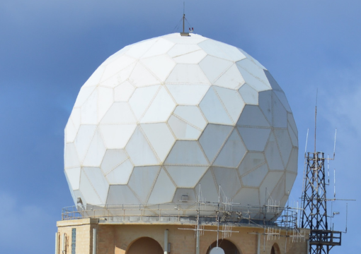
Earth Station Radome
AFC Radomes’ are a weatherproof geodesic prefabricated building structure that protects radar and antenna systems from extreme weather: wind, blowing sand, snow, ice, rain, ultra violet sunlight, temperature, fungus and corrosion.
Radomes are becoming essential for protecting earth station antenna installations from the effects of global warming, which unfortunate seem to be on the increase with severity of storms, heavy rainfall, and other extreme weather events.
Without reliable weatherproofing, exposed antennas would suffer more damage, downtime, and maintenance costs. Radomes also help to conserve energy, lower operational expenses, and reduce environmental impact. Antennas are often located in remote and hard-to-reach areas, where repairing and maintaining them is costly and challenging due to weather and road conditions.
Radomes shield antennas from wind, sand, snow, ice, rain, UV radiation, and temperature fluctuations, which can impair system performance, reliability, and uptime.
AFC’s high technology all dielectric Radome capability combines the expertise of materials science, geodesic domes, prefabricated building structures and electromagnetics. AFC manufactures six types of dielectric Radomes: TM; SL; 2L; SFC; CLS; and THS.
Each Radome technology type behaves as an electrical filter constrained to support environmental and wind load requirements. Recent technology innovations CLS and THS provide simultaneously high frequency, Ka-band, broadband and very high wind structural performance. The six technology types identify themselves primarily by the Radome wall construction, which are incorporated into Spherical, Geodesic, Silo or Stealth Radome geometries. For dual-pol polarimetric weather radar, Stealth introduces a unique technology where the Radome exhibits identical performance independent of radar polarization and pointing direction.
The superior performance and advantages of AFC’s Radome technology are evident in the worldwide Defense Satellite Communications System (DSCS, WGS, MET, GBS, MILSTAR, SBIRS), weather satellite and radar, air surveillance radar and Satcom Communications applications.
- TM: The thin membrane wall Radome where adjacent panel flanges carry all the wind loads.
- CL: The solid laminate wall Radome.
- 2L: Adding a layer of foam to the inside thin membrane wall Radome forms a 2-layer sandwich wall Radome. Foam thickness is chosen primarily for thermal insulation objectives.
- SFC: The composite 3-layer sandwich foam core wall Radome. Core thickness is chosen for the highest RF signal frequency and thermal insulation.
As part of the Radome panel molding fabrication process, the dielectric panel edges are reinforced into flanges for adjacent panel assembly. When assembled to the other panels, the panel array forms a truncated spherical Radome surface. After assembly, the Radome dielectric panel flanges form a framework establishing the general terminology Dielectric Space Frame (DSF) for AFC’s Radome products. Depending on Radome wall parameters, adjacent panel flanges may also serve as environmental load bearing beams or struts. Each panel is a molded one piece unit without bond or seam lines. Individual panels may be doubly curved or flat yielding a faceted or spherically smooth appearance. Radome applications include radar and weather radar systems, air traffic control, telemetry, satellite communications, DSCS, MILSTAR, MET, SBIRS, NOAA, NASA and receive-only listening systems.
Not commonly known to most engineers, Radome transmission loss is composed of the insertion loss from the RF signal passing through the radome wall and from the scattering loss off the panel flange framework. In most cases, the scattering loss from the framework is several times greater than the wall insertion loss.
To reduce scattering loss, AFC engineers pioneered a technique known as impedance matching to “tune out” framework scattering loss. RF circuit elements are laminated into the dielectric flanges to impedance match scattering loss. Any of the six radome technology types may be impedance matched.
To enhance radome RF performance, a filter design process implements a stronger structure at maximum rated wind speed with improved RF operation. This filter, made real by one of the six dielectric radome technology types, determines that our radomes have appropriate structural safety factors for the lifetime of the Radome. It is for this reason that AFC defines Radome structural safety by a General Buckling criterion based on the geometric deformation of the Radome shell, which defines a catastrophic failure wind speed.
